

The original IBM-PC's Parallel Printer Port had a total of 12 digital outputsand 5 digital inputsaccessed via 3 consecutive 8-bit ports in the processor's I/O space.
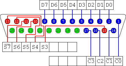
| Signal name | Register bit | D-SUB | Centronics |
| Pin | Pin | ||
| Data bit 0 | D0 | 2 | 2 |
| Data bit 1 | D1 | 3 | 3 |
| Data bit 2 | D2 | 4 | 4 |
| Data bit 3 | D3 | 5 | 5 |
| Data bit 4 | D4 | 6 | 6 |
| Data bit 5 | D5 | 7 | 7 |
| Data bit 6 | D6 | 8 | 8 |
| Data bit 7 | D7 | 9 | 9 |
| nError (nFault) | S3 | 15 | 32 |
| Select | S4 | 13 | 13 |
| PaperEnd | S5 | 12 | 12 |
| nAck | S6 | 10 | 10 |
| Busy | S7 | 11 | 11 |
| nStrobe | C0 | 1 | 1 |
| nAutoLF | C1 | 14 | 14 |
| nInit | C2 | 16 | 31 |
| nSelectIn | C3 | 17 | 36 |
| Ground | GND | 18-25 | 19-30 |
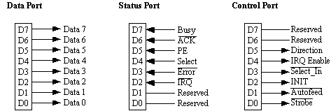
The following is typical.
       Printer         Data Port        Status          Control
	LPT1            0x03bc          0x03bd          0x03be
	LPT2            0x0378          0x0379          0x037a
	LPT3            0x0278          0x0279          0x027a
Visual Basic |
Visual Basic: In Visual Basic you have to use a DLL to access the ports. Jan Axelson programmed two DLLs which allow you to use the Visual basic 16-bit and 32-bit . You can download the DLLs at Inpout16.DLL and Inpout32.DLL. Although the program code to call the Inp and Out routines. You can also download our examples PrinterPort for Visual Basic 3.0: PRINT16.ZIP You can also download our examples PrinterPort for Visual Basic 5.0: PRINT32.ZIP Instructions to read and write to the port: read instruction:xx=INP(address) write insruction:OUT(address),xx You can write to the data port(D0-D7) at the base address. D0 is the least significant bit and D7 is the most significant bit. For example "OUT(889),85" writes 01010101(=85 decimal)to the port address 378h (= 889 decimal). You can read the status port(S3-S7) at the base address+1. At Bit 7(S7) you will read the inverted signal of the connector. S0 - S2 are usually not in use and read as low signals. When all signals are high you will read 78h (01111000 = 120decimal = 78h). You can write to the control port(C0-C3) at base address+2. The bits 0,1 and 3 are inverted so if you write 04h (00000100), all four bits will be going high and when you write 0Bh (00001011) all four bits will be going low. |
|
 |
| Global OutPort | '&H378, &H278 or &H3BC |
| Global InPort | '&H379, &H279 or &H3BD |
| Global RValue | 'Decimal value for Reference Divider |
| Global RDivider | 'Binary value for Reference Divider |
| Global SValue | 'Desimal value for Swallow Counter |
| Global SDivider | 'Binary value for Swallow Counter |
| Global NValue | 'Decimal value for Frequency Divider |
| Global NDivider | 'Binary value for Frequency Divider |
| Global PValue | '0 = 128/129 and 1 = 64/65 |
| Sub UpdateNDivider() | |
| 'Used to calculate Binary value | |
| Dim Digit | 'Number of Binary digit to S and N divider |
| Dim BinValue | 'Binary value |
| Dim TempValue | |
| Dim DecValue | 'Decimal value |
| 'Calculate Binary value for Swallow Counter | |
| DecValue = Val(SValue) | |
| BinValue = "" | |
| Do | |
| TempValue = DecValue Mod 2 | |
| BinValue = CStr(TempValue) + BinValue | |
| DecValue = DecValue \ 2 | |
| Loop Until DecValue = 0 | |
| SDivider = BinValue | |
| 'Calculate Binary value for NDivider | |
| DecValue = Val(NValue) | |
| BinValue = "" | |
| Do | |
| TempValue = DecValue Mod 2 | |
| BinValue = CStr(TempValue) + BinValue | |
| DecValue = DecValue \ 2 | |
| Loop Until DecValue = 0 | |
| NDivider = BinValue | |
| 'Used to transmit Swallow Counter digit to PLL | |
| Dim c As Integer | |
| Dim d As Integer | |
| 'Used to transmit NCounter digit to PLL | |
| Dim e As Integer | |
| Dim f As Integer | |
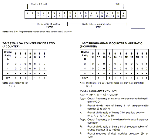
| 'Send NDivider value to PLL | Bit 8 to 18 |
| For e = 1 To (11 Len(NDivider)) | 'If number of Binary <11 digit |
| Out (OutPort), 0 | 'Set Data Low. |
| Out (OutPort), 1 | 'Set Clock High. |
| Out (OutPort), 0 | 'Set Clock and Data Low. |
| Next e | |
| For f = 1 To Len(NDivider) | |
| Digit = Mid$(NDivider, f, 1) | |
| If Digit = 0 Then Out (OutPort), 0 | 'Set Data Low. |
| If Digit = 0 Then Out (OutPort), 1 | 'Set Clock High. |
| If Digit = 0 Then Out (OutPort), 0 | 'Set Clock and Data Low. |
| If Digit = 1 Then Out (OutPort), 2 | 'Set Data High. |
| If Digit = 1 Then Out (OutPort), 3 | 'Set Clock High. |
| If Digit = 1 Then Out (OutPort), 0 | 'Set Clock and Data Low. |
| Next f | |
| 'Send SCounter value to PLL | Bit 1 to 7 |
| For c = 1 To (7 Len(PDivider)) | 'If number of Binary <7 digit |
| Out (OutPort), 0 | 'Set Data Low. |
| Out (OutPort), 1 | 'Set Clock High. |
| Out (OutPort), 0 | 'Set Clock and Data Low. |
| Next c | |
| For d = 1 To Len(SDivider) | |
| Digit = Mid$(SDivider, d, 1) | |
| If Digit = 0 Then Out (OutPort), 0 | 'Set Data Low. |
| If Digit = 0 Then Out (OutPort), 1 | 'Set Clock High. |
| If Digit = 0 Then Out (OutPort), 0 | 'Set Clock and Data Low. |
| If Digit = 1 Then Out (OutPort), 2 | 'Set Data High. |
| If Digit = 1 Then Out (OutPort), 3 | 'Set Clock High. |
| If Digit = 1 Then Out (OutPort), 0 | 'Set Clock and Data Low. |
| Next d | |
| 'Send Control-bit LSB | Control-bit = 0 |
| Out (OutPort), 0 | 'Set Data Low |
| Out (OutPort), 2 | 'Set Clock High |
| Out (OutPort), 0 | 'Set all bit Low |
| 'Send LE | |
| Out (OutPort), 4 | 'Set EN High |
| Out (OutPort), 0 | 'Set all bit Low |
| End Sub | |
| Sub UpdateRDivider() | |
| 'Used to calculate Binary value |
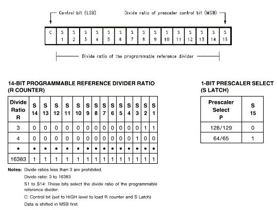
| Dim Digit | 'Number of Binary digit to R divider | Dim BinValue | 'Binary value | Dim TempValue | Dim DecValue | 'Decimal value | | 'Calculate Binary value | DecValue = Val(RValue) | BinValue = "" | Do | TempValue = DecValue Mod 2 | BinValue = CStr(TempValue) + BinValue | DecValue = DecValue \ 2 | Loop Until DecValue = 0 | RDivider = BinValue | | 'Send Prescaler Control bit to R-divider | Bit 15 | Out (OutPort), 2 | 'Set Data High (ControlBit = 1). | Out (OutPort), 3 | 'Set Clock High. | Out (OutPort), 0 | 'Set all bit Low | | 'Used to transmit digit to PLL | Dim i As Integer | Dim j As Integer | | 'Send Reference Divider value to PLL | Bit 1 to 14 | For j = 1 To (14 Len(RDivider)) | 'If number of Binary <14 digit | Out (OutPort), 0 | 'Set Data Low. | Out (OutPort), 1 | 'Set Clock High. | Out (OutPort), 0 | 'Set Clock and Data Low. | Next j | | For i = 1 To Len(RDivider) | Digit = Mid$(RDivider, i, 1) | If Digit = 0 Then Out (OutPort), 0 | 'Set Data Low. | If Digit = 0 Then Out (OutPort), 1 | 'Set Clock High. | If Digit = 0 Then Out (OutPort), 0 | 'Set Clock and Data Low. | | If Digit = 1 Then Out (OutPort), 2 | 'Set Data High. | If Digit = 1 Then Out (OutPort), 3 | 'Set Clock High. | If Digit = 1 Then Out (OutPort), 0 | 'Set Clock and DataLow. | Next i | | If SValue = 128 Then Out (OutPort), 0 | 'Set Data Low. | If SValue = 128 Then Out (OutPort), 1 | 'Set Clock High. | If SValue = 128 Then Out (OutPort), 0 | 'Set Clock and Data Low. | | If SValue = 64 Then Out (OutPort), 2 | 'Set Data High. | If SValue = 64 Then Out (OutPort), 3 | 'Set Clock High. | If SValue = 64 Then Out (OutPort), 0 | 'Set Clock and DataLow. | | 'Send Control-bit LSB | Control-bit = 1 | Out (OutPort), 1 | 'Set Data High | Out (OutPort), 3 | 'Set Clock High | Out (OutPort), 0 | 'Set all bit Low | | 'Send LE | Out (OutPort), 4 | 'Set EN High | Out (OutPort), 0 | 'Set all bit Low | End Sub | |