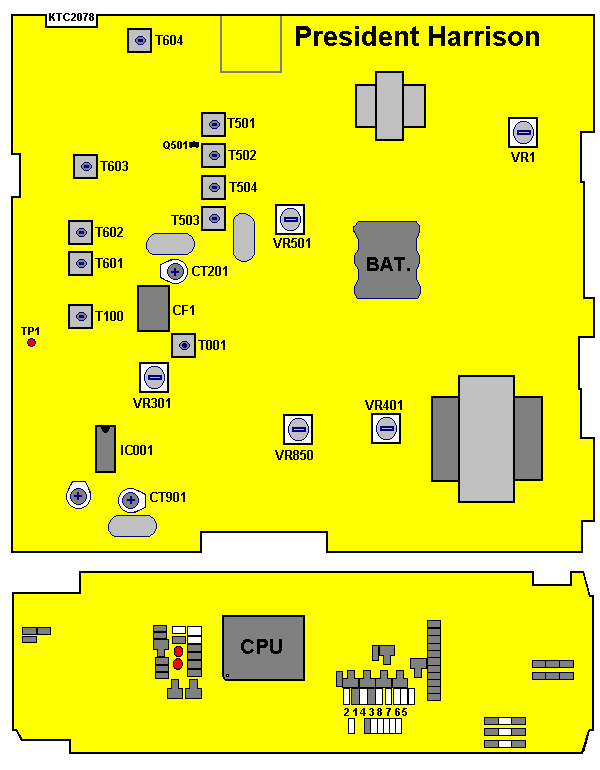

| Power Supply: 13,2 V | RF Power Meter | Oscilloscope | Audio Generator |
| Frequency Counter | Spectrum Analyzer | 50 ohm Load |
| Step | Setting | Connection | Adjust | Adjust for |
|---|---|---|---|---|
| 1 | RF Driver stage Mode: Transmit Volume: Optional Squelch: Optional Channel: 19 | Connect Oscilloscope to base of Q602 | T601 T602 | Adjust for maximum wave-form on the oscilloscope |
| 2 | RF Power stage Mode: Transmit Volume: Optional Squelsch: Optional Channel: 19 | Connect dummy-load and RF Power-meter to external ANT-jack | T604 | Adjust for maximum indication on the RF Power-meter |
| 3 | Second harmonic check Volume: Optional Squelch: Optional Channel: 19 | Connect RF Power-meter with dummy-load to spectrum analyzer | At no modulation compare the level of fundamental freq-spectrum to the level of harmonic freq-spectrum. Supression of the 2nd harmonic freq. level must be lower than -54dBm. | |
| 4 | Frequency check Mode: Transmit Volume: Optional Squelch: Optional Channel: 19 | Connect dummy-load and Frequency-counter to ANT-jack. | CT901 | Make sure that the indication of the transmit frequency is 27.185 MHz +/- 300 Hz. |
| 5 | Max. modulation check Mode: Transmit AM Volume: Optional Squelch: Optional Channel: 19 | Connect dummy-load and Modulation-meter to ANT-jack. | VR401 | Adjust so that the indication of the Modulation-analyzer is 90% with +/- 5% tolerance at high power mode. |
| 6 | Max. deviation check Mode: Transmit FM Volume: Optional Squelch: Optional Channel: 19 | Connect dummy-load and Modulation-meter to ANT-jack. | VR401 | Adjust so that the indication of the Deviation-analyzer is 2 kHz with +/- 0,2 kHz tolerance at high power mode. |
